
The following will be discussed on how to assemble a computer, especiallyfor those just learning .. from a few references that I learned .. then thefollowing will be explained step by step how to assemble a computer, hopefully useful ..


Motherboard mounted to the chassis with screws and holder (standoff). Installation the following ways:
Determine the mounting position of the hole for each plastic and metal. Holes for the metal holder (metal spacers) characterized by a ring on the edge of the hole.
Attach metal or plastic holder on the tray casing according to the position of eachcorresponding mounting holes on the motherboard.
Place the motherboard on the tray so that the head casing holder out of the holes on themotherboard. Replace the locking screw on each metal holder.
Attach frame I / O ports (I / O sheild) on the motherboard if any.
Replace the casing tray that is mounted on the motherboard with screws and lockcasing.
Some kind of casing is equipped with power supply. When the power supply installationis not included then the following ways:
Insert the power supply on the shelf at the back of the casing. Attach the four lockingscrews.
Connect the power connector from the power supply to the motherboard. ATX powerconnector types have only one way of installation so as not to be reversed. For non-ATXtype connector with a separate two-wire the black ground wires should be placed side by side and mounted in the center of the motherboard power connector. Connect the power cord for the fan, if using a fan for cooling the CPU.


Components of computer assemblers are available on the market with a wide selection of quality and price. By assembling your own computer, we candetermine the type of component, capabilities and facilities of the computer according kebutuhan.Tahapan in computer assembly consists of:
A. preparation
B. assembly
C. testing
D. Troubleshooting
A. preparation
B. assembly
C. testing
D. Troubleshooting
 |
| Add caption |
Preparation
Good preparation will facilitate the assembly of the computer and avoid potential problems associated. This preparation include:
Computer Configuration Determination
Preparation of components and supplies security
Computer Configuration Determination
Configuring the computer hooked up with the determination of the components and features of the computer and how all components work as a computer system. Choose components starting from the type of processor, motherboard and other components. Factors suitability or compatibility of the components on the motherboard must be considered, because each type of motherboard supports the type of processor, memory modules, ports and I / O bus that is different.
Preparation Components and Supplies
Computer components and equipment for the assembly is prepared for the assemblyprepared in advance to facilitate assembly. Prepared equipment consists of:
Computer components
Completeness of components such as wires, screws, jumpers, screws, etc.
Manuals and reference books of the components
The tools in the form of flat and philips screwdriver
Software operating system, device drivers and application programs.
The book takes as a reference manual to know the position of the element connectiondiagram (connectors, ports and slots) and element configuration (jumpers and switches)and how to setting jumpers and switches are suitable for computer or CD assembled. Diskette Software needed to install the Operating System, device driver from thedevice, and application programs on a computer that is assembled.
Security
Security measures needed to avoid problems such as damage to components by staticelectric charge, fall, or spill fluid. Prefent excessive heat damage due to static electricity by:
Using anti-static bracelet or touch the metal surface on the chassis before handlingcomponents to remove static charge.
Do not touch directly the electronic components, connectors or circuit track but holding the metal or plastic body found on the component.
Assembly
Stage of the process on a computer assembly comprising:
Preparing the motherboard
Replacing the processor
install the heatsink
Replacing the Memory Module
install the motherboard on the casing
Replacing the Power Supply
Replacing the Motherboard Cables and Casing
install the Drive
Install the adapter card
Final settlement
A. Preparing the motherboard
Check the motherboard manual to locate the jumper settings for CPU speed, speed multiplier and input voltage to the motherboard. Set a jumper in the blanks, set thejumper fault voltage can damage the processor.
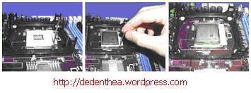
2. Replacing the processor
More easily be installed before the processor motherboard occupies the casing. How to install the processor socket and slot types are different. This type of socket.
Determine the position of pin 1 on the processor and the processor socket on themotherboard, generally located at the corner marked with dots, triangles, or indentations.
Enforce the position of the locking lever to open the socket.
Insert the processor into the socket by first aligning the position of the legs of the processor with the socket holes. Squeeze until there are no gaps between the processorwith the socket.
Lower the locking lever back.
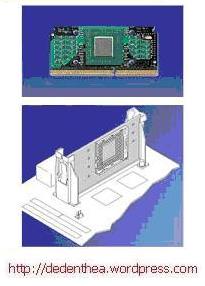
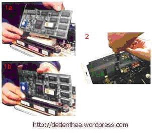
Slot types
Replace buffer (bracket) at the two ends of the slots on the motherboard so that the position of the peg holes with a hole in the motherboard meet
Insert the pegs on the peg and locking peg holes
Slide the card between the retaining processor and press into the hole to the right slot.
Replace buffer (bracket) at the two ends of the slots on the motherboard so that the position of the peg holes with a hole in the motherboard meet
Insert the pegs on the peg and locking peg holes
Slide the card between the retaining processor and press into the hole to the right slot.
3. Replacing the heatsink
Function of heatsink is to remove the heat generated by the processor through theconduction of heat from the processor to optimize heat transfer heatsink. For the heat sink should be fitted tightly on the top of the processor with some of the retaining clipon the heatsink while the contact surface coated conductor genes hot. If equipped with a fan heatsink then the power connector on the fan is connected to the fanconnectors on the motherboard.
Function of heatsink is to remove the heat generated by the processor through theconduction of heat from the processor to optimize heat transfer heatsink. For the heat sink should be fitted tightly on the top of the processor with some of the retaining clipon the heatsink while the contact surface coated conductor genes hot. If equipped with a fan heatsink then the power connector on the fan is connected to the fanconnectors on the motherboard.
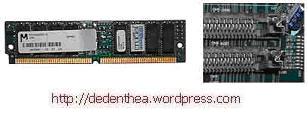
4. Replacing the Memory Module
Memory modules are generally installed in order from smallest socket number. The order of installation can be seen from the diagram motherboard. Each type of memory modulethat is SIMM, DIMM and RIMM can be distinguished by the position of the grooves on thesides and bottom of the modul. Methode set for each type of memory module as follows.
Type of SIMM
Adjust the position of a notch on the module with the bumps in the slot.
Insert the module by making an oblique angle of 45 degrees to the slot
Push the module straight up in the slot, the locking lever on the slot will automatically lock the module.
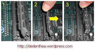
Type of DIMM and RIMM
How to install the DIMM and RIMM modules together and there's only one way that will not be reversed because there are two grooves as a guide. The difference in DIMM and RIMM position of the curve
Lay the hook on the end of the locking slot
adjust the position of the grooves on the connector module with the bumps in the slot. and insert the module into the slot.
Latch automatically locks the module in the right slot when the module is installed.
5. Replacing the motherboard on the casing
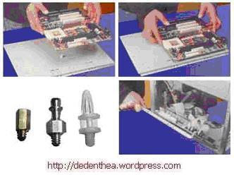
Motherboard mounted to the chassis with screws and holder (standoff). Installation the following ways:
Determine the mounting position of the hole for each plastic and metal. Holes for the metal holder (metal spacers) characterized by a ring on the edge of the hole.
Attach metal or plastic holder on the tray casing according to the position of eachcorresponding mounting holes on the motherboard.
Place the motherboard on the tray so that the head casing holder out of the holes on themotherboard. Replace the locking screw on each metal holder.
Attach frame I / O ports (I / O sheild) on the motherboard if any.
Replace the casing tray that is mounted on the motherboard with screws and lockcasing.
6. Replacing the Power Supply
Some kind of casing is equipped with power supply. When the power supply installationis not included then the following ways:
Insert the power supply on the shelf at the back of the casing. Attach the four lockingscrews.
Connect the power connector from the power supply to the motherboard. ATX powerconnector types have only one way of installation so as not to be reversed. For non-ATXtype connector with a separate two-wire the black ground wires should be placed side by side and mounted in the center of the motherboard power connector. Connect the power cord for the fan, if using a fan for cooling the CPU.
8. install the Drive
The procedure to install the hard disk drive, floppy, CD ROM, CD-RW or DVD is the same as follows:
Pellet dislodged drive bay cover (space to drive the casing)
Enter from the front drive bay with the first set the jumper settings (as master or slave) on the drive.
Adjust the position of the screw holes on the drive and the casing and replace thescrews holding the drive.
Connect the cable to the drive and the IDE connector on the motherboard (the connectoris used first primary)
Repeat steps 1 through 4 for each installation of the drive.
If the IDE cable connected to the du drive jumper settings make sure the differences are both the first drive set as master and the other as slave.
Secondary IDE connector on the motherboard can be used to connect two additionaldrives.
Floppy drive is connected to a special connector on the motherboard floppy
Connect the power cord from the power supply to each drive.
9. Install the Adapter Card
Common adapter card is installed for video cards, sound, network, modem and SCSIadapters. Video card should generally be mounted and installed prior to installing an adapter card adapter other. How:
Hold the adapter card at the edges, avoid touching the components or electronic circuits. Press the right card to plug into the expansion slot on the motherboard
Replace the retaining screw to the chassis card
Reconnect the internal cables to the card, if any.
10. Final settlement
Replace the chassis cover by sliding
connect the cable from the power supply into a wall socket.
Plug the monitor into the video card port.
Plug the telephone cord into the modem port if any.
Connect the keyboard cable and plug the mouse into the mouse port or serial poert(depending on the type of mouse).
Connect external devices such as speakers, joystick, and the microphone when thecorresponding port. Check the manual of the adapter card to make sure the location ofthe port.
Testing
The new computer is assembled can be tested by running the BIOS setup program.How to do the testing with the BIOS program as follows:
Troubleshooting
A common problem in computer assembly and handling include:
Computer or monitor is not lit, probably caused by a switch or power cord disconnected.
Card adapter is not detected due to the installation of card not fitting into the slot /
LED of the hard disk, floppy or CD is on hold due to wrong wiring connectors or pins arenot connected right. Good luck and I hope helpful.
The new computer is assembled can be tested by running the BIOS setup program.How to do the testing with the BIOS program as follows:
- Turn on the monitor and system unit. Note the display monitor and the sound from the speakers.
- FOST program of the BIOS will automatically detect the hardware installed dikomputer. If there are errors then display a blank monitor and the speaker emits an audible as an indication of the error code. Check the reference BIOS code to find an error indication in question by a beep code.
- If no error occurs then the monitor displays the execution of the POST program. ekaninterrupt the BIOS according to the instructions on the screen to enter the BIOS setupprogram.
- Check out all the hardware detection by the BIOS setup program. Some settings mayhave changed in value, especially the capacity of hard drives and boot sequence.
- Save the changes to the settings and exit BIOS setup.
- After exiting the BIOS setup, the computer will load the Operating System in accordancewith the order of the search settings in the BIOS boot sequence. Insert the bootablediskette or CD containing the operating system to drive the search.
Troubleshooting
A common problem in computer assembly and handling include:
Computer or monitor is not lit, probably caused by a switch or power cord disconnected.
Card adapter is not detected due to the installation of card not fitting into the slot /
LED of the hard disk, floppy or CD is on hold due to wrong wiring connectors or pins arenot connected right. Good luck and I hope helpful.


Post a Comment
Please, Comment here..